Engineering Summary
- Use V/F control only. Set voltage, frequency, speed, current, and pole count to the values on the spindle nameplate.
- Do not connect the spindle directly to power. ATC spindle motors must run through a correctly matched VFD.
- Install the spindle only within the marked clamping zone, keep compressed air dry and dust-free, and stop the spindle completely before tool release.
- Cooling flow, air pressure, VFD parameters, and sensor wiring must be checked before the first production run.
This manual explains how to install, commission, operate, and maintain a motorized spindle with automatic tool change (ATC). It covers inspection, mounting, electrical and pneumatic connections, cooling, variable frequency drive (VFD) setup, run-in, and troubleshooting. Complete the installation checks before starting the spindle, then follow the staged run-in procedure before production.
Quick safety rules
Observe these four safety rules before installation and throughout operation:
Warning — Control mode: Use V/F control only. Do not select vector control or a vector-performance mode. Incorrect drive settings can damage the motor windings.
Warning — Power supply: Drive the spindle through a correctly matched VFD. Never connect it directly to mains power; doing so can destroy the motor windings.
Warning — Tool release: Never press the manual tool-change button or command pneumatic tool release while the spindle is rotating. Wait until it has stopped completely. A released tool can be ejected and cause serious injury as well as damage to the drawbar, gripper, and bearings. Verify the tool-change safety interlocks before operation.
Warning — Electrical safety: Electrical work must be performed by qualified personnel. Isolate the power supply and follow the VFD manufacturer’s discharge procedure before working on wiring. Verify the spindle nameplate, VFD terminals, protective earth connection, and safety interlocks before energizing the system.
Pre-use inspection before installation
Complete the following checks before mounting the spindle. Resolve specification mismatches, missing accessories, and transport damage before proceeding:
Package and spindle condition
Inspect the packaging and spindle for transport damage, impact marks, damaged connectors, bent pneumatic fittings, and scratches on the taper. Protect the precision-ground taper from impacts and contamination.
Nameplate verification
Check the spindle nameplate against the order specifications. Verify rated voltage, power, rated frequency, maximum frequency, rated speed, pole count, and rated current. Check that the VFD supports these values and V/F control. Resolve missing or mismatched specifications before installation.
Fastening hardware and accessories
Check the supplied documentation, quality certificates where provided, circular electrical connectors, and pneumatic fittings. Inspect accessible screws and cylinder fasteners for loose or missing parts. Resolve any problems before installation.
Reading the spindle nameplate before VFD setup
Use the spindle nameplate to set the VFD. Check each setting in the table before commissioning:
| Nameplate item | What it decides | Setup rule |
|---|---|---|
| Voltage | VFD output voltage and compatibility with the spindle’s voltage rating | Match the nameplate voltage: set 220 V for a 220 V spindle and 380 V for a 380 V spindle. |
| Power and current | VFD sizing, cabinet load, and protection settings | Follow the label and match the inverter rating to the real motor. |
| Rated frequency | The rated operating point used for the V/F settings | Follow the spindle nameplate rather than copying values from another model. |
| Maximum frequency and RPM | Maximum speed limit and commissioning ceiling | Set the VFD maximum according to the label and machine limits. |
| Pole count | Speed calculation and motor setup logic | Use the pole count printed on the spindle label. |
| Control mode | VFD control method | Use V/F control. Do not use vector control. |
Never copy another spindle’s parameter sheet without checking every field. Incorrect frequency or voltage settings can overheat and damage the motor windings.
Mechanical installation guidelines
Improper mounting can deform the spindle housing and alter bearing preload, causing vibration and premature bearing failure even when the electrical wiring is correct:
1. Clamp only in the marked zone
Clamp the spindle only within the mounting zone marked on the housing. Tighten the mounting bolts to the specified torque. Excessive clamping force or clamping outside this zone can deform the housing, affect the bearings, and cause overheating.
2. Protect the taper and front housing
Protect the taper and front housing from tool strikes and workshop contamination. If an air-seal inlet is fitted, connect its air supply and keep it active during operation to keep dust, chips, and coolant mist out of the front bearing area. Keep this protection active during horizontal operation.
3. Maintain clean, dry ambient conditions
Install the spindle away from standing water, direct coolant wash, and combustible materials. Supply filtered, dry, oil-free compressed air. Drain the filter and check it regularly for water and contamination.
4. Verify machine envelope and clearances
Before tightening the mounting bolts, check the body diameter (for example, 100 mm or 125 mm), Z-axis travel, tool magazine clearance, cable carrier bend radius, and hose and tube routing throughout the machine’s full range of motion.
Electrical, pneumatic, and cooling connection map
Complete the power, sensor, pneumatic, and cooling connections before startup:
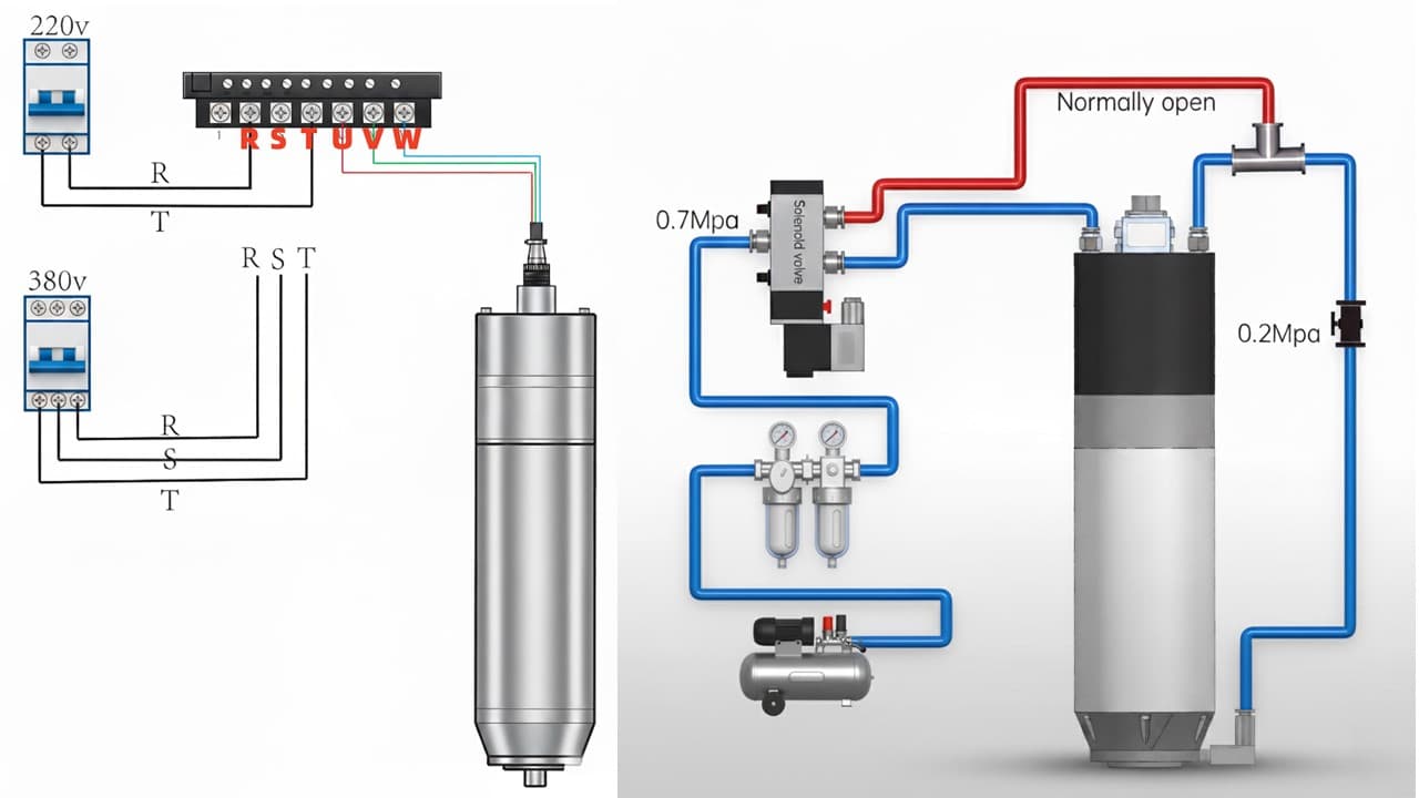 0.8 MPaSolenoid valveNormally open
View the full-size diagram
0.8 MPaSolenoid valveNormally openSpindle power connections and pneumatic valve circuit.
Rear pneumatic and coolant connections
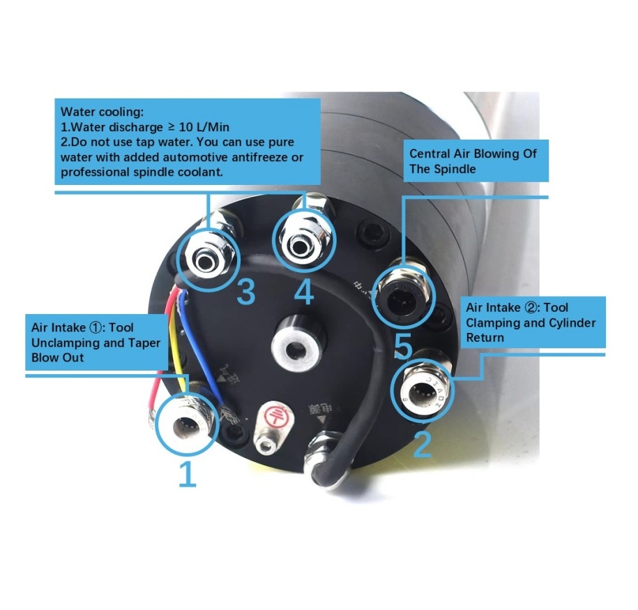
Identify the numbered ports before connecting the air and coolant lines:
View the full-size diagram
Rear spindle pneumatic and coolant connections.
| Port | Function | Connection |
|---|---|---|
| 1 | Tool release and taper cleaning | Connect the pneumatic line for tool release and taper blow-out. |
| 2 | Tool clamping and cylinder return | Connect the pneumatic line for clamping and cylinder return. |
| 3 and 4 | Coolant connections | Connect the coolant supply and return lines to these ports. |
| 5 | Central air blow | Connect the spindle’s central air-blow supply. |
Keep the pneumatic lines and coolant hoses separate. Do not connect a coolant hose to a pneumatic port.
VFD to spindle power lines
Connect the spindle motor to the VFD output terminals U, V, and W, never directly to mains power. Match the spindle connector pins and motor phases to the model-specific wiring diagram.
Tool-state proximity sensors
Check whether the proximity switches use PNP (sourcing) or NPN (sinking) outputs and match them to the controller inputs. Identify the 24 V+ and 24 V− supply terminals and the tool-clamped and tool-unclamped signal terminals before connecting them to the CNC controller.
Pneumatic tool release
Supply filtered, dry, oil-free compressed air at 0.8 MPa to the tool-release cylinder through a two-position, five-port solenoid valve. Test clamping and unclamping with the spindle completely stationary.
Cooling circulation loop
Connect the coolant inlet and outlet correctly. For spindles rated below 5.5 kW, maintain a coolant flow of 5–8 L/min. For spindles rated 5.5 kW or above, maintain 10 L/min. Do not use tap water. Use purified water with automotive antifreeze or a coolant formulated for spindles. Keep the passages clear and route the tubing without kinks. Check the flow and inspect for leaks before starting the spindle.
Pre-startup connection checklist
| Connection area | Manual rule | Before startup check |
|---|---|---|
| VFD output to spindle | Do not connect the spindle directly to power; use V/F control through the matched VFD. | Verify U/V/W, grounding, voltage, rated frequency, maximum frequency, and pole count from the actual label. |
| Tool-state sensors | Match PNP or NPN outputs to the controller input type. | Verify the 24 V+ and 24 V− terminals and test clamped and unclamped signals with the spindle stopped. |
| Pneumatic tool release | Use filtered, dry, oil-free air at 0.8 MPa and a two-position, five-port solenoid valve. | Test manual release, return to the clamped state, and sensor feedback before production. |
| Cooling loop | Connect the inlet and outlet correctly. Below 5.5 kW: 5–8 L/min. At 5.5 kW or above: 10 L/min. | Check flow, leaks, coolant cleanliness, tubing, and temperature before extended running. |
Electrical and signal wiring details
Identify each terminal on the spindle connector, VFD, and controller before connecting the cables:
VFD output connection
Identify the motor-phase and protective earth (PE) contacts from the spindle connector pinout. Connect the motor phases to VFD outputs U, V, and W, and connect PE to the protective earthing system. Verify every contact before making connections.
Grounding and cable discipline
Connect the spindle’s protective earth terminal, the VFD, and the cabinet to the machine’s protective earthing system as specified in the electrical design. Protective earthing and cable shielding serve different functions; follow the VFD manufacturer’s instructions for both. For further guidance, see the VFD EMI shielding and grounding guide.
Proximity sensor wiring logic
Match the sensor’s PNP or NPN output type to the controller inputs. Identify the +24 V DC supply, 0 V DC return, and signal outputs from the sensor wiring diagram. The usual lead colors are brown for +24 V DC, blue for 0 V DC, and black or white for signal outputs; verify the terminal assignments before connecting them. Test the tool-clamped and tool-unclamped signals before connecting them to programmable logic controller (PLC) inputs.
Controller command source separation
Check the active run-command and speed-reference sources before diagnosing a startup fault. Depending on the installation, commands may come from the operator panel, a 0–10 V analog signal, or Modbus over RS485. Check drive settings and field wiring separately. For the available control methods, see the VFD Modbus vs 0-10V speed control guide.
Pneumatic tool release and cooling system checks
Complete the pneumatic and cooling checks before running the spindle, even if the electrical wiring is ready:
| System | Manual guidance | What to verify |
|---|---|---|
| Tool-release air | Set the tool-release pressure to 0.8 MPa. | Measure pressure at the spindle and check that the air is filtered, dry, and oil-free. |
| Solenoid valve | Use a two-position, five-port valve for tool release. | Check the air-line connections and test manual release and clamping. |
| Air and water tubing | Use 8 mm air tubing and cooling tubing with an 8 mm outside diameter (OD) and 6 mm inside diameter (ID). | Check fitting size, bend radius, and leak-free routing. |
| Cooling flow | Below 5.5 kW: 5–8 L/min. At 5.5 kW or above: 10 L/min. | Check flow before startup and keep the coolant and passages clean. |
| Tool change state | Release the manual tool-change button and check that the spindle returns to the clamped state. | Test clamped and unclamped sensor feedback and the tool-change interlocks. |
For clean air supply requirements, review the ATC spindle air quality and FRL setup guide. For water chiller sizing, consult the spindle water cooling setup guide.
VFD parameter setup notes
Set the inverter strictly from the physical spindle nameplate, not from an unverified parameter list copied from another machine:
Use V/F control: Set the control mode to V/F only. Do not use vector control. Keep motor auto-tuning disabled unless it is part of the spindle’s specified commissioning procedure.
Follow the spindle label for electrical values: Set motor voltage, rated frequency, maximum frequency, RPM, current, and poles according to the actual nameplate. Do not reuse another spindle’s parameter sheet.
Set acceleration and deceleration times: Set both times to 10 to 15 seconds. Check for overcurrent trips during acceleration and stable stopping during deceleration.
Set the motor category: If the VFD has a motor-category setting, select the high-speed or variable-frequency motor option specified for the spindle. Set rotation direction separately.
For command-source setup, see the ATC spindle VFD parameter setup guide.
Staged startup and run-in procedure
Use a controlled startup sequence to verify the air supply, cooling, VFD operation, rotation direction, and tool-state signals:
Step 1: Pre-run system verification
Before commanding rotation, check the tool-release pressure of 0.8 MPa and the coolant flow: 5–8 L/min below 5.5 kW, or 10 L/min at 5.5 kW or above. Verify the VFD settings, protective earth continuity, and active run-command and speed-reference sources.
Step 2: Confirm rotation direction
View the spindle from the tool end, looking into the spindle, and jog it at low speed. Check that clockwise (CW) or anticlockwise (CCW) rotation matches the cutting tool’s required direction. Stop and correct any mismatch, then check the direction again before increasing speed.
Step 3: Gradual speed ramp-up
For a new spindle or one that has been unused for a long time, run at 3,000 RPM for 15 minutes, then increase the speed by 6,000 RPM every 15 minutes without exceeding the lowest maximum speed rating of the spindle, machine, tool holder, and tool. Reduce the final increment if necessary to stay within that limit. Before starting, confirm that all components permit operation at 3,000 RPM. Monitor the spindle throughout the run-in. For daily warm-up, see the ATC spindle warm-up G-code script. Before running a warm-up program, check all speed commands and confirm that the program matches the controller and permitted speed limits.
Step 4: Monitor sound, vibration, and temperature
Monitor sound, vibration, speed, and housing temperature throughout startup. Stop immediately if the housing temperature rises abnormally, or if you detect abnormal noise or vibration, a burning smell, unstable speed, or unexpected tool-release behavior.
Troubleshooting matrix
Use the checks below to diagnose startup and operating faults. Before servicing, stop the spindle and prevent unexpected restart. Secure the tool holder and restrain parts that could move as air pressure is released. Isolate the electrical and pneumatic supplies. Follow the VFD discharge procedure and the service procedure for releasing trapped air. Electrical work must be performed by qualified personnel; internal spindle work must be performed by authorized service technicians. Record the VFD fault code before resetting the drive.
| Symptom | Likely cause | First checks |
|---|---|---|
| No rotation or humming | Incorrect VFD parameters, phase loss, damaged wiring, or wrong command source. | Check VFD setup, U/V/W wiring, run command, frequency command, and cable continuity. |
| High noise or low precision | Incorrect clamping, worn bearings, collision damage, taper contamination, or poor tool-holder seating. | Stop and check the marked mounting zone, taper cleanliness, tool-holder condition, and impact history. Do not keep running a noisy spindle to diagnose it. |
| Smoke or overheating | Restricted cooling, incorrect V/F settings or voltage, excessive coolant temperature, or overload. | Stop and isolate the system. Verify cooling and nameplate-based settings; have qualified personnel assess insulation before restarting if damage is suspected. |
| A nut loosens during startup or stopping | Incorrect rotation direction, an unsuitable deceleration setting, or a mechanical retention fault. | Stop and inspect the loose fastener and its retaining components. Repair the fault before restarting, then check rotation direction and deceleration settings. |
| Drive trips shortly after startup | Possible moisture-related insulation fault, an unsuitable acceleration time, overcurrent, or incorrect parameters. | Record the VFD fault code and isolate the system. If moisture or insulation damage is suspected, have qualified personnel inspect it before restarting. Recheck acceleration and nameplate settings; do not repeatedly reset the drive. |
For dedicated tool release fault isolation, consult the ATC spindle tool release troubleshooting guide. For runout inspection methods, see the ATC spindle runout measurement troubleshooting guide.
Maintenance habits and warranty protection
Prevent avoidable damage by keeping the spindle clean, maintaining cooling, mounting it correctly, matching the drive settings, and following safe operating procedures:
Precision handling
Handle the spindle as a precision assembly. Protect the taper bore, electrical connector, sensor leads, and front bearing area from impacts and contamination during transport and installation.
Coolant cleanliness and channel maintenance
Replace coolant at the specified intervals and keep the cooling passages clear. Check coolant condition, flow, and temperature regularly; inadequate cooling can damage the bearings and motor insulation.
Authorized service only
Have bearing replacement, internal lubrication, and disassembly carried out by authorized service technicians. Do not dismantle the spindle or adjust internal components yourself; this can affect spindle balance and bearing preload.
Process load limits
Keep cutting loads within the spindle’s approved operating limits. Excessive depth of cut, incorrect voltage, phase loss, direct mains connection, or unsuitable VFD settings can permanently damage the spindle.
Frequently Asked Questions
Can I use vector control on an ATC spindle motor?
No. Use V/F control only. Set the VFD voltage, frequency, speed, current, and pole count to the values on the spindle nameplate.
Can an ATC spindle be connected directly to power?
No. Do not connect the spindle directly to power. It must be driven by a suitable VFD, otherwise the motor coils can burn.
What air pressure is required for ATC tool release?
Set the tool-release air pressure to 0.8 MPa. Use filtered, dry, oil-free compressed air and test tool release and clamping with the spindle completely stopped.
What cooling flow should be checked before running the spindle?
For spindles rated below 5.5 kW, maintain a coolant flow of 5–8 L/min. For spindles rated 5.5 kW or above, maintain 10 L/min. Check the flow before starting the spindle, keep the coolant clean, and prevent kinks or blockages in the cooling circuit.
How should a new or long-unused spindle be run in?
Run at 3,000 RPM for 15 minutes, then increase the speed by 6,000 RPM every 15 minutes without exceeding the lowest maximum speed rating of the spindle, machine, tool holder, and tool. Reduce the final increment if necessary to stay within that limit. Confirm that all components permit operation at 3,000 RPM before starting. Monitor coolant flow, air pressure, vibration, and VFD operation throughout the run-in.
Related Categories
Related Engineering Guides
CNC Spindle Warm-Up G-Code Script
Why cold-starting a high-speed spindle at 24000 RPM destroys bearings. Copy-ready G-code warm-up scripts, thermal equilibrium principles, and daily operating discipline for ceramic and steel bearing ATC spindles.
ATC Spindle Air Quality and FRL Setup
How moisture and oil contamination destroy ATC spindle drawbars, disc springs, and bearings. Covers ISO 8573-1 air quality standards, FRL unit configuration, refrigerated dryers, and proper filtration chain setup.
CNC Spindle Maintenance: 7 ATC Uptime Habits
Seven daily, weekly, and monthly maintenance habits that prevent ATC spindle bearing failure, rust, runout degradation, and overheating. A practical maintenance checklist for CNC router operators and shop managers.